

1U Averter: build document
The Foxfield Instruments Averter is a 1U bipolar attenuverter. When no signal is connected to the input, +5V is normalised to it, meaning the tile will act as a -5V-+5V voltage source.
Like all Foxfield Instruments' tiles, it’s specifically designed for DIY assembly.
The Averter is designed using surface-mount components (“SMD/SMT”). It all may look small, but with a little patience you’ll be fine. That said, we definitely do not recommend this as your first DIY kit. You should be reasonably confident with a soldering iron before moving onto SMD kits. If you’ve built a few kits and know your way around a soldering iron, though, you should be fine.
FOXFIELD TILES ARE NOT COMPATIBLE WITH INTELLIJEL 1U SYSTEMS. Apologies. We write this in bold quite a lot. There’s more in a footnote if you’re interested why.
Note
Owing to a production error, early kits went out with an eight-pin TL072 IC in your Bag B, rather than a fourteen-pin TL074. You should be supplied with a TL074 with your order, either in the bag or attached. If you do not have a fourteen pin TL074 IC, drop us a line immediately and we’ll get one sent to you ASAP. Do not attempt to attach the eight-pin TL072; it will not work.
Table of Contents
- Specification
- What’s in your kit
- What you’ll need to build your kit
- Before you begin
- How to solder SMD components
- Building your kit
- Connecting your tile to power
- Usage ideas
- Appendix
Specification
- Format: “Pulp Logic 1U” - NOT COMPATIBLE WITH INTELLIJEL 1U SYSTEMS
- Power connector: Pulp Logic “Tile Tail”.
- Width: 6HP
- Power consumption: 16mA +12V, 13mA -12V
What’s in your kit
Inside the paper bag are some small plastic bags. To avoid confusion around resistor and capacitor values, we’ve separated out components that might otherwise be confusing. If there are identical looking components, count the number on a strip; you should never have two components that can be confused.
We would not recommend tipping all your bags out into the same space; you will get confused. Remove components as you need them. Similarly, do not remove components from their tape until you’re ready to attach them - the components are very small.
| Quantity | Part | Marked/Description | Location |
|---|---|---|---|
| 4 | 100k resistors | `1003`` | Bag A |
| 2 | 100n capacitor | yellow 1206 capacitor | Bag A |
| 2 | Fuse | 1206 compoment marked with a letter ('B') | Bag A |
| 2 | Diode | small black block with two metal legs | Bag A |
| 2 | 10u aluminium capacitor | small aluminium can | Bag A |
| 1 | 22p capacitor | yellow capacitor (no marking) | Bag B |
| 2 or 3 | 1k resistor | `1001` | Bag B |
| 0 or 1 | 3k resistor | `3001` | Bag B |
| 1 | 5mm bipolar LED | Mechanical bag | |
| 1 | TL074 IC | small chip with fourteen legs | Bag B |
| 1 | 78L05 regulator | small chip with three legs on one side, one leg on the other | Bag A |
| 1 | 100k linear potentiometer | Including washer and nut | Mechanical bag |
| 2 | 3.5mm mono jacks | Including nuts | Mechanical bag |
| 1 | PCB | PCB bag | |
| 1 | Panel | PCB bag | |
| 4 | M3 screws | Mechanical bag | |
| 1 | Knob | Mechanical bag | |
| 1 | Tile tail | Paper bag |
If you find a TL074 chip attached to the packaging: this is to replace an in correct component supplied inside Bag B. More details further on in the build guide.**
What you’ll need to build your kit
Foxfield Instruments kits may use surface-mount components, but they’re designed to be assembled by humans with hand-tools.
We list the tools we recommend that you’ll need on our DIY page.
How to solder SMD components
If this is your first SMD kit, you might want to go over our up-to-date guide to soldering SMD components. We’ve collated some videos and guides from around the web, which should prove instructive.
Before you begin
- Read through these instructions to get an idea of where you’re going.
- Dig out all the tools and equipment you’ll need. Having things ready is better than diving into doors with a busy workbench.
- Clear your workspace.
- (optional) Make a cup of tea. Don’t keep it too near the workbench, but tea always makes DIY go easy.
- Get your soldering iron up to temperature.
- OK, let’s begin!
Building your kit
Throughout this build document, we’ll refer to the front and back of the PCB. The front is where the jacks and pot go: it’s got the outlines of them on it. The back is where the majority of the components are, and where the Foxfield logo is.
We’re going to start with the back of the board.
1. IC (TL074 op-amp)
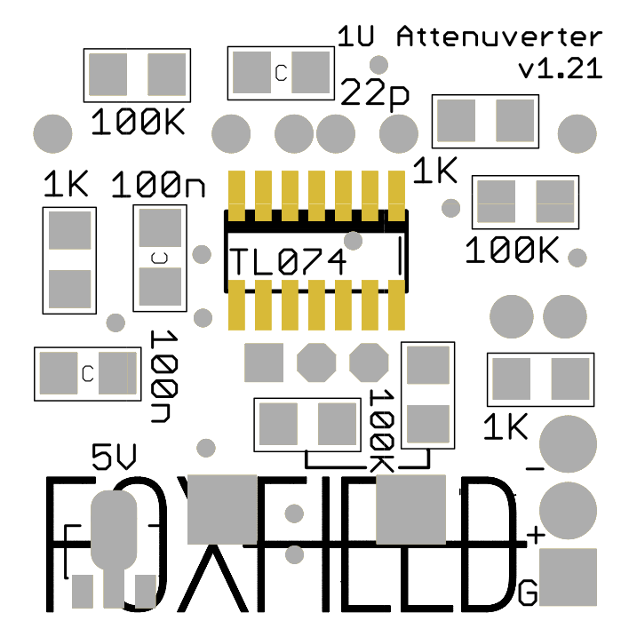
Solder the op-amp first.
Note
Owing to a production error, early kits went out with an eight-pin TL072 IC in your Bag B, rather than a fourteen-pin TL074. You should be supplied with a TL074 with your order, either in the bag or attached. If you do not have a fourteen pin TL074 IC, drop us a line immediately and we’ll get one sent to you ASAP. Do not attempt to attach the eight-pin TL072; it will not work.
Much like through-hole, we solder SMD components in height order - lowest to highest. However, with our tiles, we make one adjustment to that build order: solder the IC first. It’s the hardest thing to solder, and it’s in the middle of the board - if we put it on now, we’ll have the most room to work.
The IC must be fitted in the correct direction. There are two clues to its directionality: the vertical line at one of the short ends of the silkscreen, and the horizontal line that intersects the pads at the upper edge of the board (away from the Foxfield logo).
If your IC has a white line printed along a short edge, this should correspond to the short white line on the board.
Regardless, you’ll also notice - if you look at the chip end-on - that it has one slanted edge and one vertical edge. The slanted edge is also hinted on the PCB silkscreen - in this case, it faces away from the Foxfield Logo.
2. Bottom Passives and Diodes
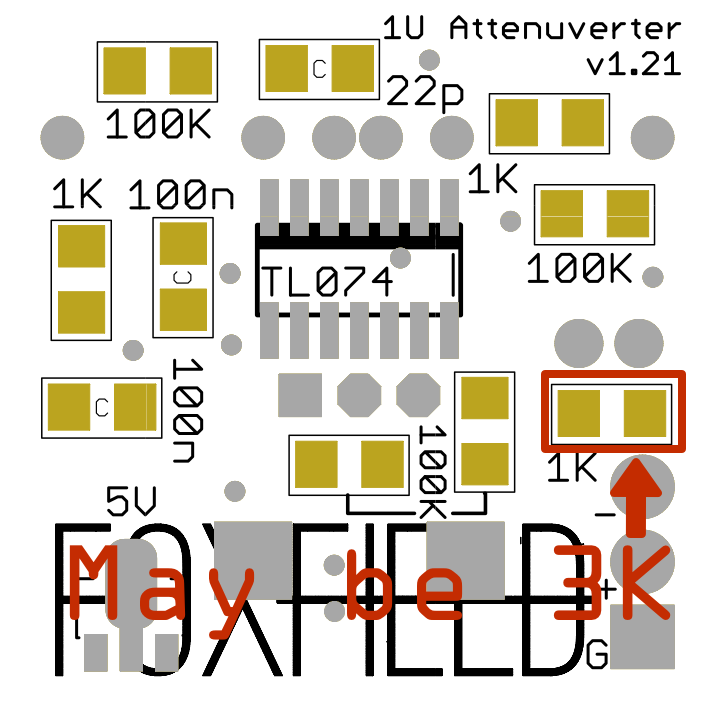
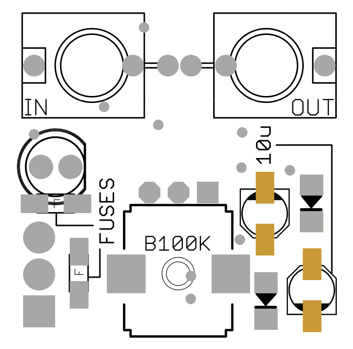
Solder the 1206 passive components into the correct places
Now you’ve got the IC in, attach all the 1206-sized resistors and capacitors. These are all marked with their values; the capacitors have a C in the middle of their outline. Note that one of the capacitors has a capacitance of 22p, and the other two have 100n - be sure to get them in the right places.
NB: you may have a 3k resistor - marked 3001 - in bag B. If so, place it on the pads highlighted above, labelled on the PCB as 1k. If you have no 3k resistor, and instead have three 1k resistors in Bag B, place a 1k here as marked.
Our recommended routine for doing this would be:
- prep all the pads - solder on one side of the outlined shape
- attach all the 1206s facing in the same direction to their prepared pad
- solder up their other pad
- rotate the PCB 90º and repeat for all the 1206s in a different direction.
None of this components are directionality - back-to-front, upside-down, it doesn’t matter - although we’d recommend keeping the resistor values visible just in case you have to debug.
3. Bottom: voltage regulator
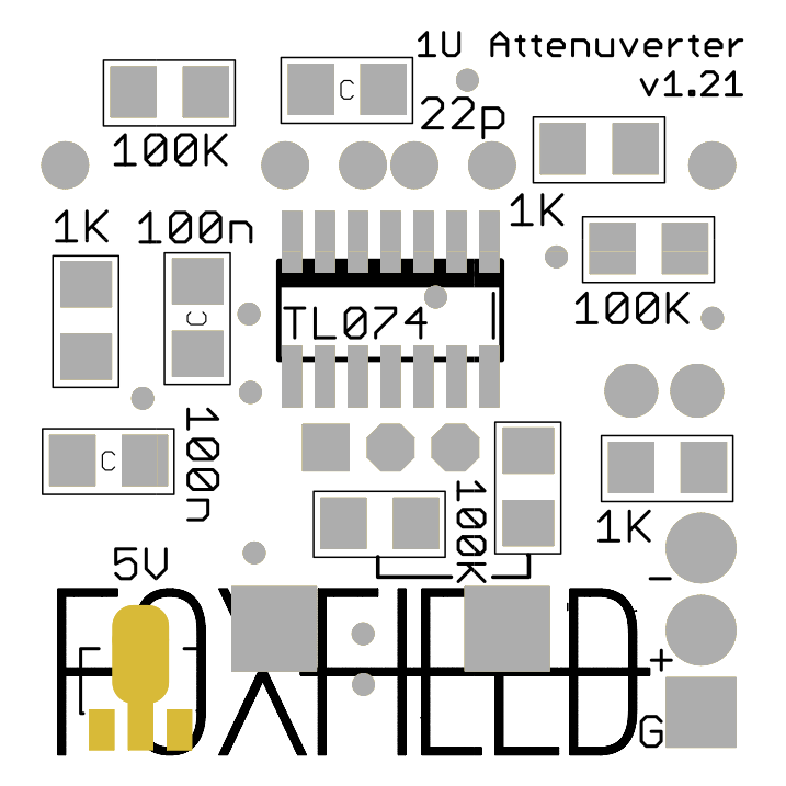
Solder the voltage regulator onto the back of the board
Finally, solder the 5V voltage regulator onto the base of the board. This is easiest to do if you use one of the ‘row of three’ pads to pin it down, rather than the wide tab on the other size. Once you’ve soldered the three pads in a row, solder the other tab to anchor it in place. This is a nice easy component to solder to finish the base of the board.
4. Topside: flat components
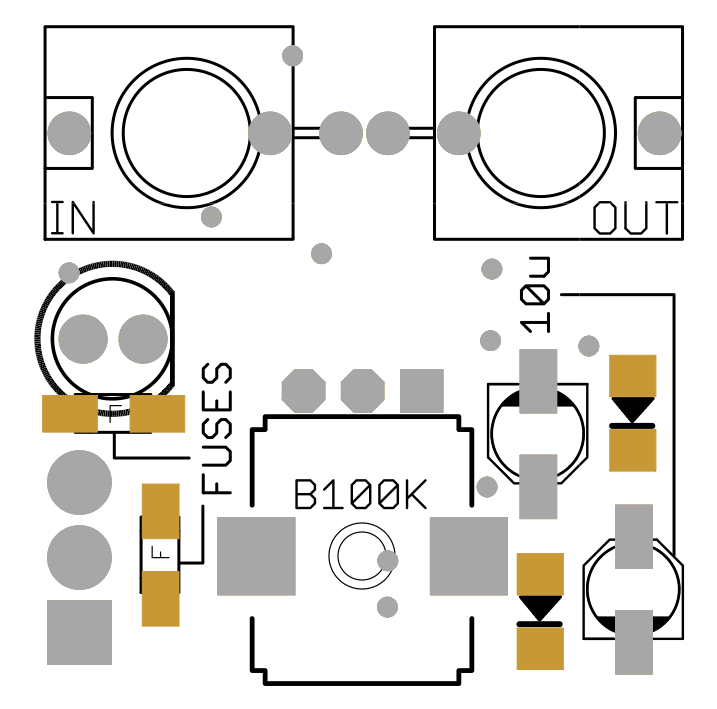
Solder the SMD components onto the top of the board
Flip the PCB over; we’re going to build up the top (the side with the jacks and pot outline on it). Now that you’ve got components on the back, you’ll need to find a way of firmly holding the PCB - just putting it on a tabletop or cutting mat is probably not enough. (A vice is really helpful).
Let’s do the flatter components first.
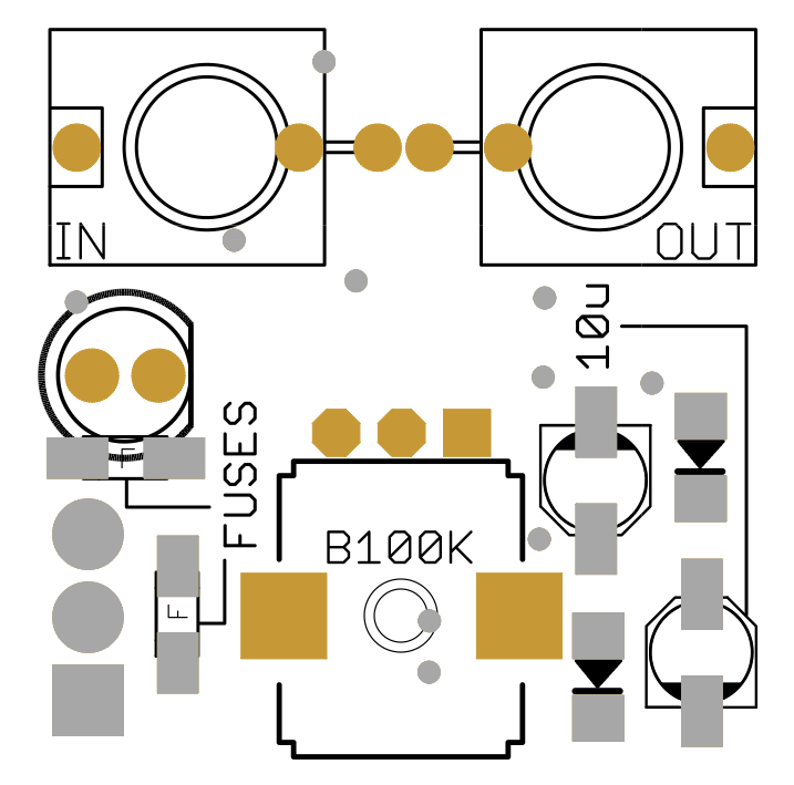
First, the fuses. These are marked with an F in the middle on the PCB and easily fitted like any other 1206 passive. They do not have a correct direction.
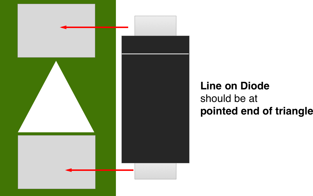
Then, the diodes. Diodes must be fitted in the correct orientation - they will not work otherwise. If you take the diode chips and look at them in good light - or shine a cellphone torch on it - you’ll see a line printed on the top, towards one end. This must match the line printed on the board. If you can only see the triangle of the diode icon in the silkscreen, the line should be at the ‘pointy end’ of the triangles
Next, the diodes. These must be fitted in the correct orientation. If you take the diode chips and look at them in good light - or shine a cellphone torch on it - you’ll see a line printed on the top, towards one end. These should go towards the pointed/narrow end of the triangles silked on the board. Imagine the line ‘completing’ the Diode symbol:
5. Topside: 10u capacitors
Solder the capacitors onto the top of the board.
Now we can fit the 10u capacitors. These must be fitted in the correct direction. Fortunately, that direction is outlined for us on the board: the base is asymmetric, and the black line on the top of the cap should match the black line on the board. They might seem a bit fiddly to solder on, but trust in the flux and you’ll be fine.
6. Topside: through-hole components
Solder all the through-hole components, being careful to align them with the board.
Now we’ll fit the jacks, and LED. This will probably be familiar from many other through-hole builds, but as a reminder:
- remove the nuts from the jacks.
- put the LED in its marked hole and do not solder it. The flat edge of the LED is marked on the board (on the inner side).
- Place the jacks into their marked positions and do not solder them.
- Take the front panel of the board and mount it onto the jacks. It should fit neatly, becoming parallel to the PCB, and pushing down until it’s at the top of the jack bodies. When you’re satisfied with its positioning, screw the jack nuts to hold them to the front.
- Confirming that the components are still flush to the board, flip the PCB over and solder the jacks in place.
- Now manoeuvre the LEDs so they sits in their hole correctly. Solder them in place and trim their legs.
7. Tile tail
Fit the power connector.
Finally, we need to fit the power connector. To do this: remove the front panel.
Separate the three wires at the end of the tail and strip them with your wire strippers.
Next, tidy and tin the ends: twist stranded core of each wire together and tin it with your soldering iron. Do not think you can get away without tinning wires. It will make your life way easier.
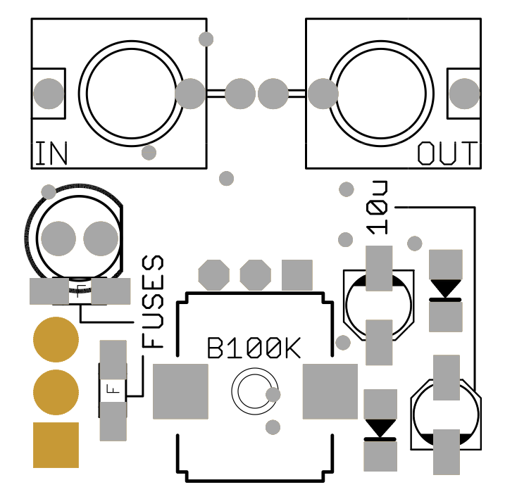
Insert the tile tail into the board. Tile tail power is configured as follows:
- black - GROUND
- red - +12V
- white - -12V
These are marked on the rear of the PCB - the ground is the square pad at the bottom of the board. Attache the wire so that it goes through from the base, and you solder it on the top-side of the board.
Trim its ends, and re-mount the panel. Turn the metal shaft of the pot all the way to the left. Take your knob, unscrew the set-screw a little, and push it down over the shaft so it lines up with the leftmost marking on the front-panel gradations. Screw the set-screw tight. You might have to lift the knob a tiny bit up from the very bottom of the shaft, so it doesn’t grind against the nut.
7. That’s it!
You’re done. You’re ready to power up your tile and test it.
Connecting your tile to power
At Foxfield, we'd **always** recommend powering up a new DIY build as the only thing connected to a power supply.If you’ve got a bench supply or testing supply, that’d be ideal (you’ll need a dual-supply +/-12V for the Attenuverter tile).
Of course, you don’t have to - and many people don’t - but we’d hate to see your modular come to grief through DIY errors.
Tile-tails are keyed; you can’t power them up the wrong way. Just connect the connectors so they’re firmly linked, and coloured cables match up.
When turned on, with nothing connected to the input, turning the knob should make the LED smoothly transition from Red to Green. Because 5V is normalised to the input, the LED represents the output transitioning from around -5V to around +5V.
When you insert a signal cable into the IN jack, the LED will now reflect the attenuated version of the signal. The OUT jack emits the voltage you can see on the LED.
Enjoy your new tile!
Usage ideas
- Use the attenuverter to control the amplitude of a signal - or invert it. For instance, use one to adjust the peak-to-peak range of an LFO, or to invert the LFO - useful for finer control of modulation.
- With nothing in the input, combine the attenuverter with a pitch CV signal in a unity mixer; the attenuverter will act as a transposition control.
- With nothing in the input, use the attenuverter as a fixed adjustable voltage source to feed into CV inputs - for instance, to give a CV control with no knob attached a physical control, or to place a permanent offset on a particular control.
Appendix
“Why don’t you support Intellijel 1U?”
Space, and personal design choices.
Intellijel 1U doesn’t just have a smaller frontpanel: it also has a smaller space between the rails for a PCB. We didn’t feel we could fit enough components onto a parallel PCB that would fit comfortably into Intellijel’s format; we decided against multi-stacked boards. The Foxfield 1U series fit what they can onto a single PCB.
Currently, pretty much all 1U DIY seems to be focused on the Pulp Logic (and Erthenvar/Synthrotek) format, so we thought we’d stick to that.
There’s also a philosophical distinction: 1u “tiles” focus on small, single-purpose, 6HP or 12HP objects; Intellijel’s 1U modules focus on wider, sometimes multi-functional units.
We appreciate this is a shame given the likely popularity of Intellijel 1U; we also suspect that Intellijel will be making a handsome and useful range of their own 1U modules, that many purchasers will be entirely satisfied with.
Needless to say: we may revisit this distinction in the future.
“What’s the different between Intellijel 1U and Pulp Logic 1U?”
The difference is: how you measure the 1U.
Pulp Logic style tiles (such as Foxfield tiles) are designed for use with lipless rails, and measure 1U from the top of the top rail to the bottom of the bottom rail.
Intellijel 1U tiles are designed for lipped rails, and measure 1U from the top of the top lip to the bottom of the bottom lip. As such, the tile panel, and gap between the rails, is smaller than Pulp Logic.
Eurorack doesn’t really have any standards; it has conventions. This is a case where two conventions emerged separately.