

Tile Tail Power Adaptor: Build Document
The Foxfield Instruments Tile Tail Power Adaptor connects to a standard Eurorack busboard to offer eight female tile-tail power connectors, suitable for any Pulp Logic compatible 1U tile (such as those made by Foxfield, Erthenvar, Synthrotek, Pulp Logic, etc).
Like all Foxfield Instruments' tiles, it’s specifically designed for DIY assembly.
Table of Contents
- What’s in your kit
- What you’ll need to build your kit
- Before you begin
- Building your kit
- Connecting your adaptor to your power bus
- Using a different power connection
What’s in your kit
All the components in your kit are in the main paper bag.
| Quantity | Part | Marked/Description | Location |
|---|---|---|---|
| 1 | PCB | Main bag | |
| 8 | Female tile tail | Main bag | |
| 1 | 2x08 Female Header | Main bag |
What you’ll need to build your kit
Foxfield Instruments kits may use surface-mount components, but they’re designed to be assembled by humans with hand-tools.
We list the tools we recommend that you’ll need on our DIY page.
Before you begin
- Read through these instructions to get an idea of where you’re going.
- Dig out all the tools and equpiment you’ll need above. Having things ready is better than diving into doors with a busy workbench.
- Clear your workspace.
- Get your soldering iron up to temperature.
- Whilst you’re doing that, make a cup of tea. Don’t keep it too near the workbench, but tea always makes DIY go easy.
- OK, let’s begin!
How to solder components
Rather than re-invent the wheel, the excellent Adafruit guide to soldering contains good, clear advice on how to solder through-hole components, along with excellent images of what good solder joints look like. Read it if you’re unsure!
Building your kit
Throughout this build document, we’ll refer to the front and back of the PCB. The front is where the tile tails come out of, and where the power connector’s solder joints are; it’s got the markings explaining the colour scheme. The back is where the power connector should be inserted, and where the tails' power connectors are soldered.
1. Solder the power connector
Insert the sixteen pin power connector from the back so it is flush with the board; solder it on the top.
2. Strip and tin the tile tails
Using your wire strippers, strip the ends of the tile tails - all three wires - and, having twisted each stranded wire, tin the wires. Tinning the wires will make it much easier to connect them to the board. Each tail should have three separate, thin, cleanly tinned wires.
The colour scheme is marked on the board, but to reiterate:
- BLACK is GND
- RED is +12V
- WHITE is -12V
Insert the tails through the front of the board, so that there is no wire protruding around the joins, and solder them on the back. Make sure the wires are flush to the front and not shorting to each other: this is a power board and you do not want to make any short circuits.
Connecting your adaptor to your power bus
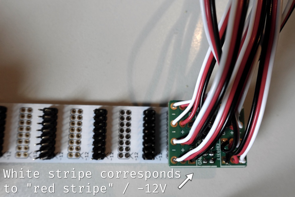
Connect the power adaptor to a spare spot on your power bus. The long white stripe on one edge of the board indicates the -12V edge of the power connector, and this should match the -12V pins on your power bus (what you might call the ‘Red Stripe’ on Doepfer-style modules).
Once connected, you’ll be able to connect up to eight tiles to your adaptor. Tile-tails are keyed; you can’t power them up the wrong way. Just connect the connectors so they’re firmly linked, and coloured cables match up.
Using a different power connection
You don’t have to use the female connector supplied. If you want, you could put a male connector on the tile, so it could connect to a standard Eurorack power cable, or to a female flying bus.
If you do this with a 2x05 male header, it should go in the 10 pins closest to the white stripe on the bottom of the board.
Also: if you mount the power on anything other than a fixed busboard, we strongly recommend covering the base of the adaptor board in electric tape; you do not want the soldered ends the power cables shorting anything else in your rack.